- Introduction of the Home Automation project
- Part 2: Setting up the Raspberry Pi
- Part 3: Building the control box
- Part 4: Securing the software
- Part 5: Public access to the service
- Part 6: Setting up the app
In the last chapter Part 2: Setting up the Raspberry Pi we looked at the software side of the project. This part included setting up the Raspberry Pi with the right OS and an remote access through SSH as well as the installation of required packages and the HomeAutomationBackend webapplication.
At this point of the project it is time to construct the HomeAutomation Remote-Control-Box. First of all two plywood plates are needed to be able to build all components together. It is also possible to use a better looking wood panel, but it is not necessary. The dimensions for the wood panels are 60×30 cm and 22×22 cm. These panels can be bought cheaply at your local construction market. For a full list of the needed components read Introduction of the Home Automation project.
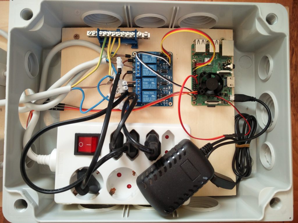
Mounting all components to the box
The smaller wood panel is used as a mounting point for the Raspberry Pi, the Relay and the internal socket strip. The Raspberry Pi and Relay can be mounted with 4 M2.5 screws each. Be sure to choose the right position, so the cables will be long enough to connect the components with each other.
To make the external power sockets controlable, the relay must interpose the connection between internal and external power supply. There are two basic types of relays:
- normally open (NO) which interrupts, when no current flows through the control circuit and
- normally closed (NC) which interrupts, when current is running through the control circuit.
As the whole software is based on an normally open relay, it is recommended to use one of these.
WARNING: WORKING ON POWERED CIRCUITS CAN GET LIFE THREATENING!
Now every single relay must be connected with the power supply and the external plug socket. These cables must be opened and the phase conductor (brown or black) connected to the relay by using ferrules and plug terminals should be used to connect the neutral conductor (blue or grey).
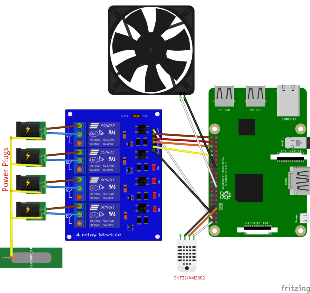
Wiring up the relays with the sockets and the Raspberry Pi
The wiring of the Raspberry Pi is shown in the following circuit plan. More information about the GPIO and WiringPi numbering of the Raspberry Pi can be found here.
Here is also a list of the wired connections:
| CON1 | CON2 | Description | Cable Color |
|---|---|---|---|
| RPi GPIO 39 | Relais module VCC | 5V-power | white |
| RPi GPIO 38 | Relais module GND | Ground | black |
| RPi GPIO 21 (WiringPi 29) | Relais module IN4 | Control circuit 4 | brown |
| RPi GPIO 20 (WiringPi 28) | Relais module IN3 | Control circuit 3 | red |
| RPi GPIO 16 (WiringPi 27) | Relais module IN2 | Control circuit 2 | orange |
| RPi GPIO 12 (WiringPi 26) | Relais module IN1 | Control circuit 1 | yellow |
| RPi GPIO 13 | RPi Fan GND | Ground | black |
| RPi GPIO 9 | RPi Fan VDD | 3.3V-power | white |
| RPi GPIO 5 | DHT22/AM2302 Sensor Ground | Ground | black |
| RPi GPIO 40 | DHT22/AM2302 Sensor VDD | 5V-power | white |
| RPi GPIO 4 | DHT22/AM2302 Sensor Data | Data connection | orange |
When desired, the source code can be downloaded from Git and edited. Change homeautomation.backend.rest.RpiDeviceState.java to add or remove relays and homeautomation.backend.rest.SensorThread.java to change the sensors used. By default the DHT22 / AM2302 sensor is configured. It measures humidity and temperature.
Part 4: Securing the software describes how to secure the Raspberry Pi, before making it accessible publicly. Be sure not to skip this part as the default configurations are not secure.
However, if you just want to use the app locally and know what you are doing, go to Part 6: Setting up the app